
Bridge planning & installation guide
The most expensive mistakes are made long before the bridge arrives. Here is how to size your bridge, choose a foundation and get it installed.
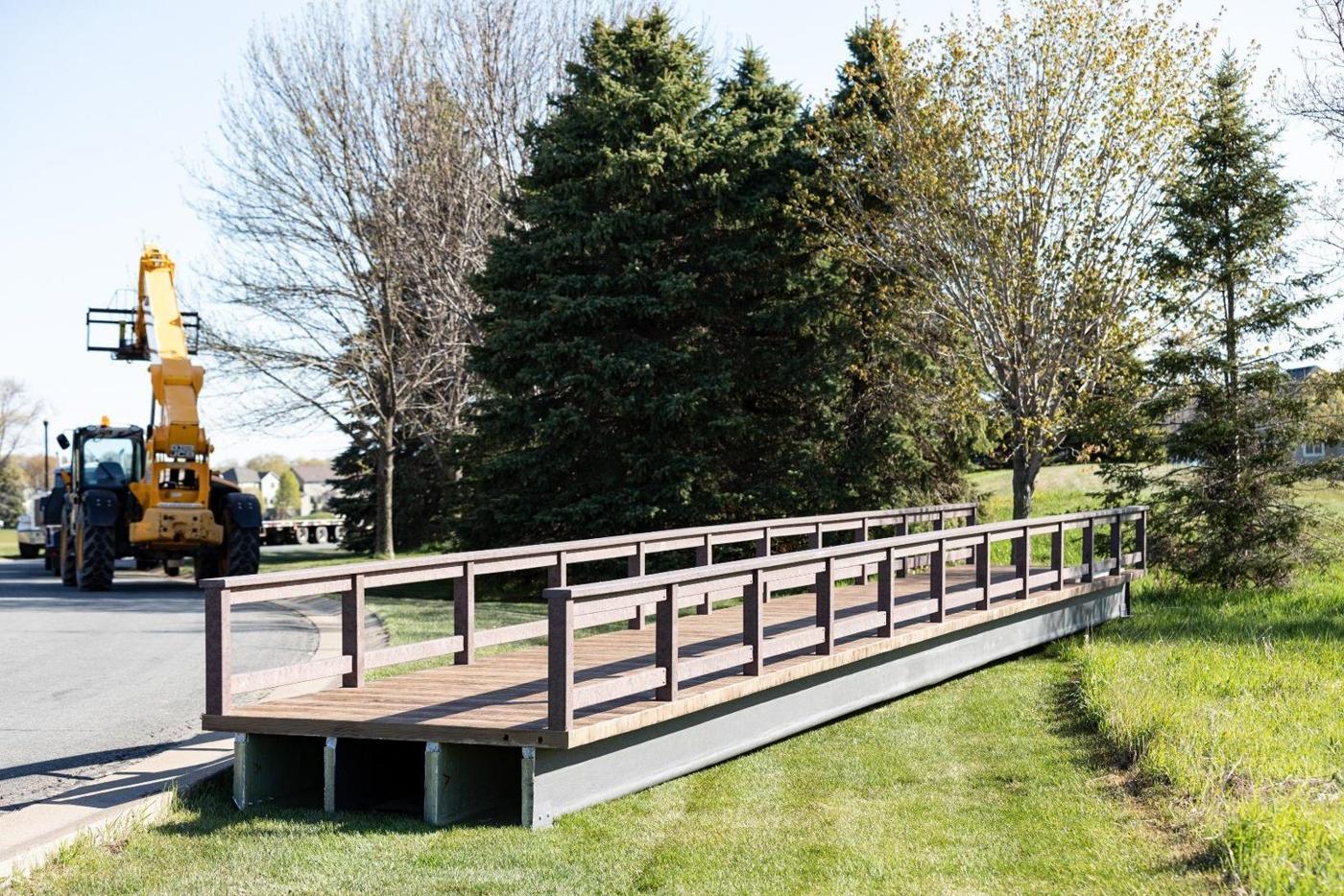
The most common (and costly) mistake
Sizing the bridge so its ends land at, or very close to, the edge of whatever it spans.
Why it drives up cost
It forces the most expensive foundation. Ends at the bank usually need concrete abutments that double as retaining walls, so excavation is at its maximum.
It draws regulatory attention. Disturbing a waterway can bring regulators who require temporary coffer dams while the foundation is dug, formed and poured.
It makes the job slower and messier. More digging, more concrete, more time and more site damage.
The fix: add 4–6 feet to the span
Make the bridge 2 to 3 feet longer at each end. The water stays undisturbed, and faster, less expensive foundations like helical piles become possible.
Foundation options
Site and bridge conditions can rule some of these out, so please confirm your choice with us.
| Option | Best suited to | Relative cost | Foundation time |
|---|---|---|---|
| Re-use existing foundations | Replacing an old bridge on sound foundations | Lowest | Minimal |
| Helical piles PREFERRED | Most sites; over 80% of our installations | Low | Same day as bridge |
| Concrete slab | Areas with no ground frost | Low | 2–4 days |
| Drilled piers | Concrete where frost depth or soils require it | Higher | 2–4 days |
| Spread footings | Extreme lateral (hurricane wind) or uplift (intense flooding) loads | Highest | 2–4 days |
| Pre-cast concrete blocks | Small residential bridges, DIY | Low | 1 day |
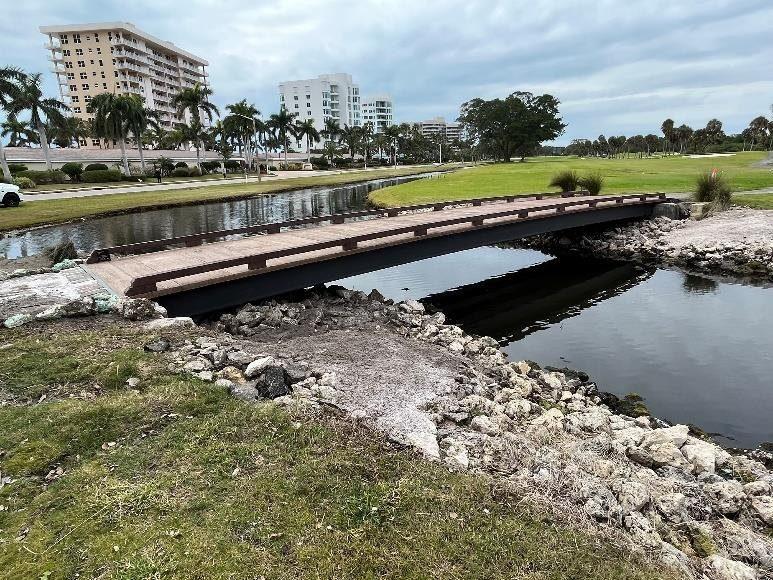
Re-using existing foundations
The most cost-effective option when you are replacing a bridge. Every Links Bridges 100% Fiberglass Bridge is custom-made, so we build to the foundations already in the ground. Send us measurements and photos early so we can confirm they are suitable.
Concrete foundations
The most familiar choice. Spread footings are large blocks with a wall on top, rarely needed for our bridges. Drilled piers are two or more cylinders per end, tied by a poured cap. A slab is poured at each end where frost isn't a factor. Pre-cast blocks suit small DIY bridges, set level on crushed stone and buried for uplift.
Helical piles PREFERRED
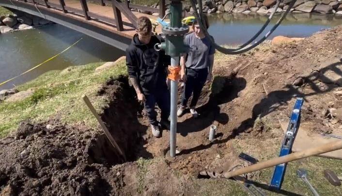
Steel shafts with a screw-like helix, driven into the ground. We almost always recommend them, and over 80% of our installations use them.
Why we recommend helical piles
Lower cost
Concrete costs are hard to predict and, in our experience, almost always higher. Sometimes considerably.
Faster install
Done in less than a day, piles included. There is no cure time. Concrete needs at least 2 days, usually 3 to 4.
Less site damage
1–2 ft of digging at each pile, all of it put back. A mini-excavator instead of 35-ton concrete trucks.
No soils report
Bearing capacity is read pile by pile as it's driven, so a geotechnical report generally isn't needed.
Installation with helical piles
Steps may vary with site conditions. Where they differ, your Technical Package governs.
Pile count
One pile per beam at each end of the bridge.
| Bridge width | Beams | Piles |
|---|---|---|
| 6 ft | 2 | 4 |
| 8 ft | 3 | 6 |
| 10 ft | 4 | 8 |
Materials & equipment
| Helical piles | Typically 7 ft long × 3 in diameter; thicker piles or extensions for unusual soils or loads |
|---|---|
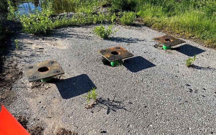
| Pile caps (one per pile) | 12 × 12 × ½ in galvanized steel, four 3/8 in holes 2 in from the corners |
| Anchor hardware | 3/8 in bolts with washers and nuts, four per pile cap |
| Fiberglass end plates | Supplied with the bridge, plus Tapcon® screws, four per beam |
| Equipment | Mini-excavator with helical drive; telehandler or crane and straps rated for the bridge weight; level; drill |
Install the helical piles
Mark each pile from your Technical Package: centered under a beam, 6 in from the beam end. Drive the piles; the top-of-pile elevation sets the bridge height, so check it against the plans. Watch back-pressure as each goes in, and add an extension if capacity is short at 7 ft. Level the tops, set a cap on each and check it with a level.
Place the bridge
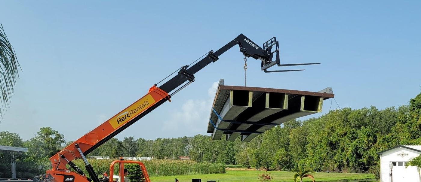
Rig it with straps rated for its weight, tucked under the curbs where the side-rail blocking leaves space, for a balanced load. Lower it so the final 1 ft of each beam end bears on its pile cap; there are a couple of inches of margin. Once foundations are ready, placing and anchoring the bridge usually takes no more than a couple of hours.
Secure the bridge
Using the cap's pre-drilled 3/8 in holes as a guide, drill up into each beam. Bolt every beam to its cap with a 3/8 in bolt, washer and nut. Then fit the supplied fiberglass end plates over the beam ends: 4 Tapcon® screws per beam, 2 on each side, pre-drilled.
Final checklist
- Piles at required bearing capacity and top-of-pile elevation
- Caps level and centered under each beam, 6 in from the end
- Final 1 ft of each beam end bearing on its cap
- Four bolts, washers and nuts tight at every cap
- End plates fastened at both ends, 4 screws per beam
- Rigging removed; deck and rails inspected
- Soil returned; site backfilled and graded
Planning a bridge project?
Call us before you finalize the span, the foundations or the schedule. The more we know about your site, the better we can help you find the most cost-effective path.